R/C model airplane electronics
(Circuits I have reproduced and can recomend for others)
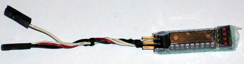
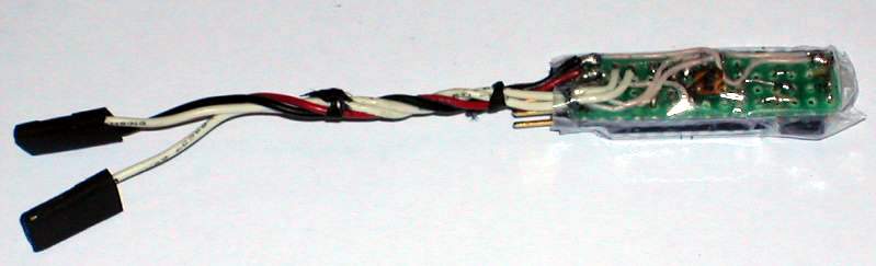
V-tail Mixer for Flying Wings
Uses PIC16F84. Documentation by Barry
http://www.theoldworkshop.freeserve.co.uk/index.htm
Here is zip file in case original webpage disappears. I used the code called mixerII.hex.
Assembly is very compact. A miniature 4MHz quartz crystal is placed under the PIC in the middle of the mounting socket. Weight of the circuit in the picture is 7 grams.
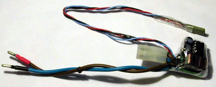
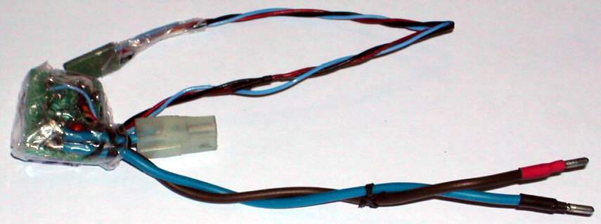
ESC PIC Motor Speed Controller
USES PIC 12C509 one-time programmable. Watchdog ON. Weight of circuit in the picture is 20 grams. Circuit originally from Mike Norton mirrored at
http://www.theoldworkshop.freeserve.co.uk/esc.htm
There is a modification from Bruce Abott http://homepages.paradise.net.nz/bhabbott/electronics.html
Personally I assembled modification from Vitaly Puzrin and used his program code http://www.rcdesign.ru/eng/electronics/
Here is his zipped documentation that I used. ESC starts after throttle is at minimum. To save space I didn’t solder empty battery detection and brake. Due to that pin 4 is connected to +5V. No FET for brake. I could bye on local market only transistors IRL2505: logical input 55V, 104 A, R = 0.008 W . Original transistors IRL2203 specifications are very little better: logical input, 30V, 116A, 0.007 W .
P.S. After 2 years, finally I decided to build an ESC using a PIC, when could not get working stable-enough analog-electronics circuits from a page http://www.capable.ca/rcstuff/escbec.htm. Sorry for a negative attitude. But the battery charger concept on this site I like a lot. See below.
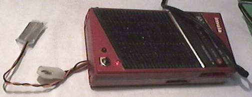
Battery charger
Homebuilt peak-detecting fast battery charger using integrated circuit Maxim Max713 (that can be obtained free of charge as a test sample from Maxim ic) sometimes malfunctioned and does not switch off. Batteries several times overheated and lost capacity. Finally I built battery charger that senses the temperature of the battery pack. Batteries get hot at the end of the charge as energy is not going to chemical reaction anymore. Then it is time to turn the charging off. It is a very safe method used in phones, cameras and computers. I have built a circuit from http://www.capable.ca/rcstuff/
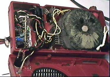
Here is a picture of my charger. The box is a little bit too small to accommodate everything. I have made a few modifications to the original circuit:
1) Put a pushbutton between thermistor lead and ground, since my charger did not go into charging mode when power was switched on. Push button starts the charging.
2) Put a green led in series with 300 ohm resistor between collector and emitter of charging current transistor. Gives trickle charge to top fill the batteries. In charging mode the charge LED is on and trickle is off. In trickle mode trickle LED is ON and charge led is OFF.
3) Used only one thermistor. Might not work in hot summer days. But I think that 50 degrees centigrade is temperature where to stop charging, but not 20 degrees above ambient temperature. Well it depends on conditions where charger is to be used. If it is used outside in cold winter the temperature may newer rise to +50 deg. C.
4) Added 7805 regulator to comparator. Increases stability if one wants to charge battery packs with different number of cells.
5) Added a LED in series with a thermistor. Indicates that thermistor wires are not open circuited. So, finally there are free LED in my charger version.
6) Added a small analogue current meter in series with battery to monitor the current.
By Janis from Riga, Latvia
A l n i s @ l a t n e t . l v